OT Security Hardware Components
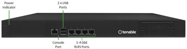
OT Security Appliance
| Component | Description |
|---|---|
| Power Indicator | Indicates when the OT Security appliance is turned on (Green) or off. |
| Console Port | Not in use |
| USB Ports | Not in use |
| Ethernet Ports |
Four GbE ports used to connect to management and operational networks as follows: Port 1 – by default, this port is used for both Management (User Interface) and as the Active Query port (that communicates with the network assets). This port configuration could be changed (both during the set up and later in the Settings page) to include just the Queries. This is done in order to separate the management interface from the controllers’ network. Port 2 – Mirror port - used as the destination of the mirroring session (SPAN). This port receives a copy of the network traffic. This port has no IP address. Port 3 – if the port separation option is enabled, this port is used for management (UI) only and can be connected to a network that is not part of the controller’s network. Port 4 - Reserved port, used by OT Security's Professional Services for remote or local support. |
Rear Panel
| Component | Description |
|---|---|
| Cooling Fans | Two cooling fans. Make sure that the fans are not obstructed. |
| Power Switch | ON/OFF switch. (Press and hold for a few seconds to turn power off.) |
| Power Supply Port | AC power connector; 100 – 240 V AC |
Package Contents
| Component | Description |
|---|---|
| Two Ethernet Cables | Two standard RJ45 Ethernet cables. Use these cables to connect the OT Security appliance to the network switch. |
| Power Supply Port | AC power connector; 100 – 240 V AC. |
| Mount Brackets | 2 x 1U rack mount brackets. |
OT Security Sensor
Rack Mount Sensor
Note: The Rack Mount sensor is being discontinued. Instead, we now offer an adapter kit that enables you to attach the Configurable Sensor model to a rack mount.
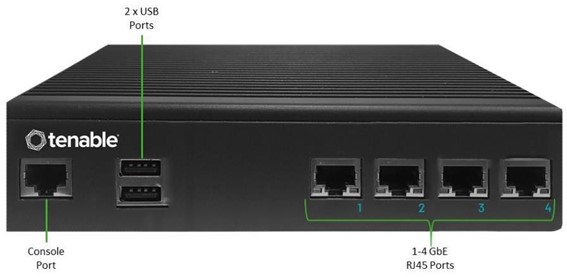
Front Panel
| Component | Description |
|---|---|
| Console Port | Not in use |
| USB Ports | Not in use |
| Ethernet Ports |
Four 1GbE ports used to connect to management and operational networks as follows: Port 1 – Management port – used for managing the device. Port 2 – Mirror port - used as the destination of the mirroring session (SPAN). This port receives a copy of the network traffic. This port has no IP address. Port 3 – Not in use. Port 4 – Not in use. |
Rear Panel
| Power Button | Stand-by mode in red; Power-on mode in green. |
| Reset Button | Reboots the system without turning off the power. |
| Power Switch | ON/OFF switch. (Press and hold for a few seconds to turn power off.) |
| Power Supply Port | AC power connector; 100 – 240 V AC |
Package Contents
| Component | Description |
|---|---|
| Ethernet Cable | A standard RJ45 Ethernet cable. Use this cable to connect the sensor to the network switch. |
| Power Cable | A standard local AC power cable. |
| Power Supply | 60W AC power adaptor; 100 – 240 V AC. |
| Mount Brackets | 2 x 1U L-shaped rack mount brackets. |
| Screws Pack |
Configurable Sensor
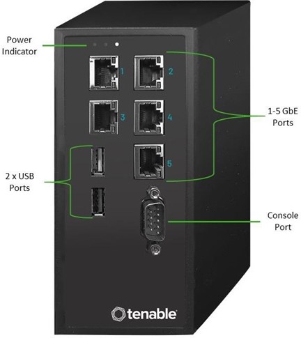
Front Panel
| Component | Description |
|---|---|
| Power Indicator | Indicates when the sensor is turned on (Green) or off. |
| Console Port | Not in use |
| USB Ports | Not in use |
| Ethernet Ports |
Five GbE ports used to connect to management and operational networks as follows: Port 1 – Management port – used for managing the device. Port 2 – Not in use. Port 3 – Mirror port - used as the destination of the mirroring session (SPAN). This port receives a copy of the network traffic. This port has no IP address. Port 4 – Not in use. Port 5 - Not in use. |
Package Contents
| Component | Description |
|---|---|
| Power Cable | A standard local AC power cable. |
| Power Supply | 60W AC power adaptor; 100 – 240 V AC. |
| Ethernet Cable | A standard RJ45 Ethernet cable. Use this cable to connect the sensor to the network switch. |
| Mounting Ears | 2 x 1U L-shaped rack mount brackets (“Ears”). |
| Screws Pack |