Set up the Sensor
You can install the configurable model sensor in a DIN rail or mount it on a standard 19-inch rack (using the “mounting ears” adapter kit).
Set up a Configurable Sensor
You can either mount the Configurable Sensor on a DIN rail or on a standard 19-inch mounting rack (using the “mounting ears” adapter kit).
DIN Rail Mounting
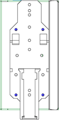
To mount the Tenable One OT Exposure Configurable Sensor on a standard DIN rail:
-
Use the bracket, located on the back of the Sensor, to mount the Sensor on to a DIN rail.
-
Connect the power using one of the following methods:
-
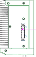
DC Power — Connect the DC power chord to the Sensor by inserting the 12-36V DC 6-pin Phoenix Contact connector into the side of the Sensor unit and tightening the embedded screws at the top and bottom of the connector. Then, connect the other end of the chord to a DC power source.
-
AC Power — Connect the AC power supply to the Sensor by inserting the 12-36V DC 6-pin Phoenix Contact connector into the side of the Sensor unit and tightening the embedded screws at the top and bottom of the connector.
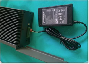
Then, insert the AC power supply cable (provided) into the power supply unit, and plug the other end into an AC outlet.
-
Rack Mounting (for Configurable model)
A Configurable Sensor can be attached to a mounting rack, using the “mounting ears” that are provided.
To mount the Configurable Sensor on a standard (19-inch) rack:
-
Prepare the unit for rack mounting:
-
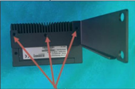
Remove 3 screws from each side of the unit.
-
Attach the "mounting ears" on both sides of the unit, using new screws (provided).
-
-
Insert the server unit into an available 1U slot in the rack.
Note:- Make sure that the rack is electrically grounded.
- Make sure that the cooling fan air intake (located in the back panel) and the air ventilation holes (on the top panel) are not obstructed.
-
Secure the unit to the rack by fastening the “mounting ears” to the rack frame using the mounting screws (provided).
-
Connect the power using one of the following methods:
-
DC Power — Connect the DC power chord to the Sensor by inserting the 12-36V DC 6-pin Phoenix Contact connector into the side of the Sensor unit and tightening the embedded screws at the top and bottom of the connector. Then, connect the other end of the chord to a DC power source.
-
AC Power — Connect the AC power supply to the Sensor by inserting the 12-36V DC 6-pin Phoenix Contact connector into the side of the Sensor unit and tightening the embedded screws at the top and bottom of the connector.
Then, insert the AC power supply cable (provided) into the power supply unit, and plug the other end into an AC outlet.
-
Connect the Sensor to the Network
OT Exposure Sensor is used to collect and forward network traffic to the Tenable One OT Exposure Appliance. To perform Network Monitoring, connect the unit to a mirroring port on the network switch, which is connected to the controllers/PLCs of interest.
To manage the sensor, connect the unit to a network. This can be a different network than the one that is used to perform network monitoring.
To connect the Tenable One OT Exposure Configurable Sensor to the network:
-
On the OT Exposure Sensor, connect the Ethernet cable (supplied) to Port 1.
-
Connect the cable to a regular port on the network switch.
-
On the unit, connect another Ethernet cable (supplied) to Port 3.
-
Connect the cable to a mirroring port on the network switch.
Access the Sensor Setup Wizard
To log in to the Management Console.
-
Do one of the following:
-
Connect the Management Console workstation (for example: PC and laptop.) directly to Port 1 of the OT Exposure Sensor using the Ethernet cable.
-
Connect the Management Console workstation to the network switch.
-
-
Ensure that the Management Console workstation is part of the same subnet as the OT Exposure Sensor (which is 192.168.1.5) or is routable to the unit.
-
Use the following procedure to set up a static IP (you must set up a static IP in order to connect to the OT Exposure Sensor):
-
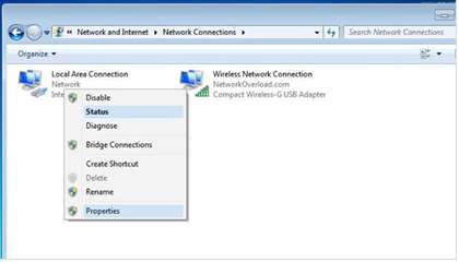
Go to Network and Internet > Network and Sharing Center > Change adapter settings.
Note: Navigation may vary slightly for different versions of Windows.The Network Connections window appears.
-
Right-click Local Area Connections and select Properties.
The Local Area Connections window appears.
-
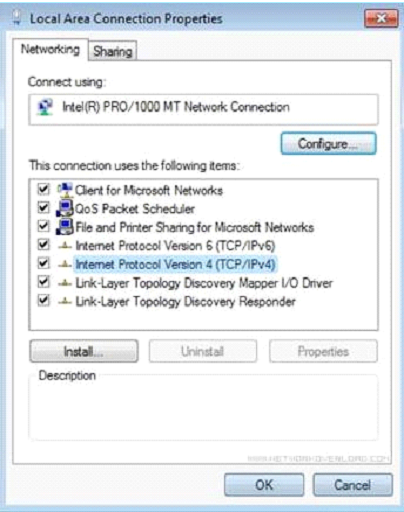
Select Internet Protocol Version 4 (TCP/IPv4) and click Properties.
The Internet Protocol Version 4 (TCP/IPv4) Properties window appears.
-
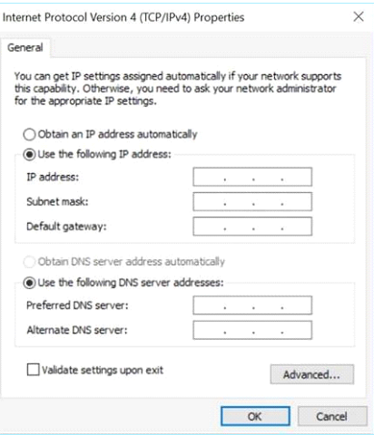
Select Use the Following IP address.
-
In the IP address box, type 192.168.1.10.
-
In the Subnet mask box, type 255.255.255.0
-
Click OK.
Tenable One OT Exposure applies the new settings.
-
-
From your Chrome browser, navigate to https://192.168.1.5:8000.
Note: The user interface can only be accessed from a Chrome browser. Use the latest version of Chrome.